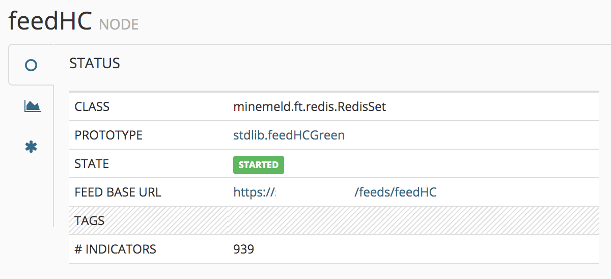
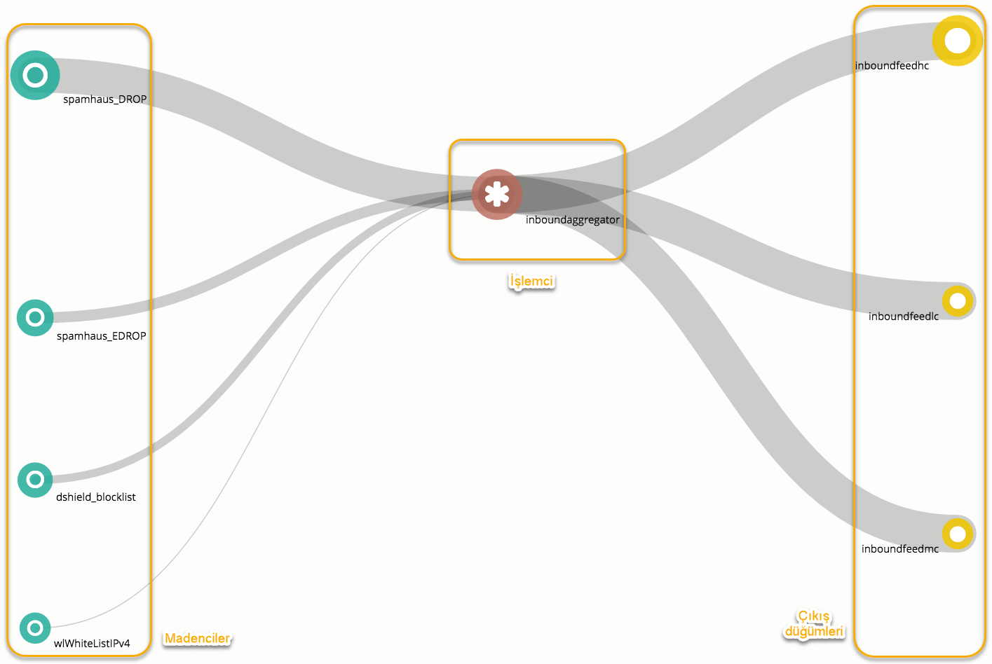
MineMeld has numerous miners for acquiring threat intel from a wide variety of sources. You then use a processor to determine what type of indicators are going to be processed from the mined data. For instance, IPv4 addresses, URLs, user-agents, file hashes (md5, sha-256, ssdeep, etc.), filenames, mutexes, registry keys, and so on. In MineMeld, the outputs of a miner node (the indicators fetched from a feed source) need to be specified as the input of other node (s). However, in Cortex XSOAR, all indicators fetched from feed integrations flow into the Cortex XSOAR instance's indicator store.
If you are working in video you will at some point find yourself using an EDL. I have found that many people barely can read an EDL so here is an explanation about what all the numbers and letters mean.
Some History
Before None Linear Editors (NLE) came into the world of video the way to edit was sitting in a room with some tape machines, an editor machine and if you needed to do dissolves and wipes even a video switcher and a audio mixer.
To do simple cuts only editing you needed one Player tape machine and one Recorder tape machine. You connected the output video from the Player to the Recorder input. Then you needed an Editor. The Editor could control the tape machines using RS-422 control interface. It’s a cable that goes to each tape machine and can control play, stop, wind, rewind, speed etc.
There have been many different Editor manufacturers and most of them aren’t existing today. One of the large ones was CMX and their EDL format has become a standard we still use today.
To do a cut you would find the In point on the Player (Source) and set IN on the Editor, then find the Out point on the Player and set OUT. After that you would set an in point on the Recorder. To see what how the cut would look like you could do a Preview, this would play the Recorder up to the cut and then switch to the input from the Player, but not record it on tape. This is because if you record and want to move the In point later there was no Roll-tool to move the edit. You had to copy the first clip to the Recorder again and then copy the new clip with the adjusted In point.
If you wanted to do a dissolve or wipe you needed two Players, a Video switcher and a Recorder. If the material you wanted to dissolve or wipe between was on the same tape you had to make a copy of the material to another tape, B-reel. You would make an edit from Player 1 to the Recorder, then select the clip to dissolve to on Player 2 and program the Video switcher to do a dissolve or wipe. The Video switcher got a signal from the Editor to do start the dissolve or wipe as well as its duration.
When hitting the record or preview button all three tape machines would rewind about 5 seconds and then play. The editor would try to get them in sync and if it succeeded it would do the edit and dissolve from Player 1 to Player 2.
Reading an EDL
This EDL is in 25 FPS and Video only, audio will be discussed later in the article.
What does it all mean?
The lines starting with a * are comments and I have removed them in the version below so it’s a bit easier to read.
row 1:
TITLE: – this is the title of the EDL, often this is the name of the Timeline in the exporting editor.
row 2:
FCM: – Frame Code Mode, this tells the receiving editing system if you have use drop frame, or non-drop frame timecode (for NTSC). There can also be a FCM Comment telling the frame rate.
Now we get to the Edits, let’s explain the different columns in each row.
column 1:
001 – number of the edit event, CMX3600 has a maximum of 999 edits.
column 2:
TAPE1 – name of the Source tape, maximum 8 characters.
column 3:
V – this tells that the edit is Video only. We will have a look at how this column can look when there is audio in the timeline further down in this article.
column 4:
C, D or W – this tells if it’s a Cut, Dissolve or Wipe. I will go into details when we go through each line of the EDL
Minemeld Edl Input Tools
column 5:
timecode for the Source In point
column 6:
timecode for the Source Out point
column 7:
timecode for the Master / Recorder In point
column 8:
timecode for the Master / Recorder Out point
Cut

Now that you know what the different columns are used for I will go through each line in the EDL.
Event “001”, Source Tape “TAPE1”, Video only, Cut.
Source starts at 00:00:32:00 and ends at 00:00:35:16
Recorder starts at 01:00:00:00 and ends at 01:00:03:16
If you compare this to the timeline you will see that the last frame of this clip on the timeline is at 01:00:03:15. In an EDL the Outpoint is always 1 frame after the last frame shown. This is because the Out point automatically will become the next clips In point. Take a look at the next row and you will see that 01:00:03:16 is the new In point on the Recorder.
Event “002”, Source Tape “TAPE1”, Video only, Cut.
Source starts at 00:00:08:16 and ends at 00:00:12:05
Recorder starts at 01:00:03:16 (previous events Recorder Out point) and ends at 01:00:07:05
Dissolve
Now let us add a dissolve. This makes the EDL a bit more complicated to read since there are two lines for the event.
The first line is for the FROM clip, the second line is for the TO clip. Since we need something to mix from the FROM clip has to be played as well. In a NLE this is the same as having handles. In a NLE the Dissolve can be places before, over and after the Cut, in an EDL it’s always after the cut.
Row 1
Event “003”, Source Tape “TAPE1”, Video only, Cut.
Source starts at 00:00:12:05 (previous events Source Out point) and ends at 00:00:12:05
Recorder starts at 01:00:07:05 (previous events Recorder Out point) and ends at 01:00:07:05
The reason it’s Cut is because we are cutting this clip to itself, then us a “switcher” to dissolve to the TO clip (row 2).
If you have a look at the in and out point you see that they have the same timecode. This is called an “open edit” , the Source player will run for the same duration as defined in the second row of the event.
Row 2
Event “003”, Source Tape “TAPE2”, Video only, Dissolve – 25 frames long.
Source starts at 00:00:19:00 and ends at 00:00:23:03
Recorder starts at 01:00:07:05 (previous events Recorder Out point) and ends at 01:00:11:08
Wipe
Next is a wipe. Wipes do have numbers that are defined by the SMPTE. The number tells the editing system which wipe to use and what direction is should go, but not if there is any softness, border etc.

As with the dissolve the event is 2 rows.
Row 1
Event “004”, Source Tape “TAPE2”, Video only, Cut.
Source starts at 00:00:23:03 (previous events Source Out point) and ends at 00:00:23:03
Recorder starts at 01:00:11:08 (previous events Recorder Out point) and ends at 01:00:11:08
Row 2
Event “004”, Source Tape “TAPE2”, Video only, Wipe number 002 – 52 frames long.
Source starts at 00:00:37:24 and ends at 00:00:42:05
Recorder starts at 01:00:11:08 (previous events Recorder Out point) and ends at 01:00:15:14
Speed change
The following clip shows how a Speed change is represented in the EDL by using a M2 event.
Row 1
Event “005”, Source Tape “TAPE1”, Video only, Cut.
Source starts at 00:00:04:07 and ends at 00:00:12:10 (which is a duration of 8:03 at 25FPS)
Recorder starts at 01:00:15:14 (previous events Recorder Out point) and ends at 01:00:23:17 (which is a duration of 8:03 at 25FPS)

So far it looks like a normal edit at 100% speed. But since there is a M2 event attached to the event the speed is not 100%.
Row 2
“M2” indicates that there is a Motion (speed) change, source Tape “TAPE1”, “012.5” frames per second (at 25FPS = 50%) with start timecode 00:00:04:07
Audio
The third column is where you can see what channels are “copied” from the source to the destination. Above we had only the Video channel (V). When adding Audio this column can look like this:
A – Audio only (no VIdeo) on channel 1
Minemeld Edl Input Definition

Then there are different ways to write the same thing, depending on what software creates the EDL you might find some of the following:
AA/V – Video and audio on channel 1 and 2
VA1A2 – Video and audio on channel 1 and 2
A12V – Video and audio on channel 1 and 2
AUD3 – Audio only on channel 3
A3 – Audio only on channel 3
VA1A2A3A4 – Video and audio on channel 1, 2, 3 and 4
The maximum amount of audio channels in a standard CMX3600 EDL is 4.
Then you can do Split edit, this is when the Video and Audio from the same source don’t start at the same time. Sometimes used to get a softer cut. If you do this there will be a row before the actual edit event telling what is delayed and by how much. Video can also be delayed.
© 2011 Nikolai Waldman